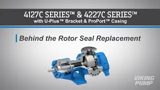
Replacing a Behind the Rotor Seal - 4127C & 4227C Series™
Have questions? We'd love to chat! Send us a message here: https://www.vikingpump.com/yt
***Download the Technical Service Manual here: https://vp.salesmrc.com/item/12498
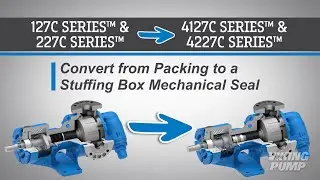
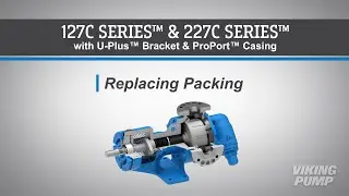
In this video we will guide you through the replacement of a behind the rotor seal in Viking Pump’s stainless-steel pumps – with U-Plus™ bracket and ProPort™ casing. To more or to see other repair videos, please visit our website at VikingPump.com.
This video applies to these pump models:
H4127C HL4127C K4127C KK4127C L4127C LL4127C
H4227C HL4227C K4227C KK4227C L4227C LL4227C
#VikingPump #modularity #serviceandrepair
▬ More Videos ▬▬▬▬▬▬▬▬▬▬▬▬
► All Viking Pump Videos: / vikingpumpinc
► Subscribe to Viking Pump Channel: https://bit.ly/2KJGmJT
▬ Social Media ▬▬▬▬▬▬▬▬▬▬▬▬▬▬▬
► Facebook: / vikingpump
► LinkedIn: / viking-pump
► Website: http://www.vikingpump.com
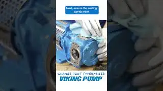
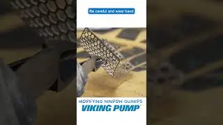
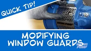
To begin, remove the stainless-steel window guards from the bracket.
Next, bend up the tang of the lock washer.
Place a brass or hardwood bar into the port opening to keep the pump from turning.
Loosen and remove the locknut. Remove and discard the lock washer.
Loosen the bearing housing set screws.
Loosen and remove the bearing housing.
Remove the bearing spacer collar. The collar may have come out with the bearing housing.
Remove the half round rings.
Loosen and remove the head capscrews.
Remove the head by tilting it backward to prevent the idler from falling off the idler pin.
Remove and discard the head gasket.
Remove the rotor shaft. A soft-headed hammer may be used to tap on the end of the shaft to aid with removal.
Loosen the four rotary seal face set screws.
Remove and discard the rotary seal face.
Next, using a tool or piece of pipe that is similar in diameter, carefully rock the stationary seal out of the bore. Discard the seal.
Remove the seal spacer ring.
Using a screwdriver and soft-headed hammer, carefully tap out the lip seal.
Clean out any old grease from the bracket.
Before reassembly, ensure the casing, bracket, head, idler pin, idler, and rotor shaft are free of any debris or wear. Replace any worn components.
To begin reassembly, lubricate and place the bracket lip seal with the spring side down – toward the casing end of the pump. Using a manual or hydraulic press and a flat fixture, fully press in the lip seal.
Install the seal installation sleeve onto the shaft.
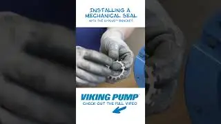
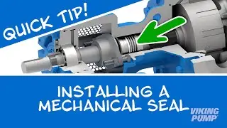
Lubricate the shaft and install the seal rotary member until it makes contact with the back of the rotor. Tighten each set screw until they just make contact with the shaft – then fully tighten the set screws.
Remove the seal clips to engage the seal.
Turn the pump up onto the bracket to aid with seal seat installation.
First, install the seal spacer ring.
Next, install the seal seat with the pins down and aligned with the grooves in the bushing. Carefully push the seal until it is fully seated against the seal spacer.
Before installing the rotor shaft, tape the threads at the end of the shaft to prevent damage to the lip seal in the bracket. Lubricate and install the rotor shaft. Take care not to damage the seal seat or lip seal during installation. Remove the tape and seal installation sleeve.
Install the half-round rings. Install the bearing spacer collar over the half round rings.
Since the seal is engaged and pushing the rotor shaft out of the pump. The bearing housing will need to be installed to aid with head installation. Install the lock washer by aligning the tab through the slot on the shaft. Install the locknut. Fully tighten the locknut. Loosen the bearing housing to open the clearance and pull the rotor into the casing.
Use care when turning the bearing housing. Stop if you encounter resistance. Turning too far may over-compress and damage the seal.
Install the head gasket. Apply appropriate gasket sealant to the head and ensure even coverage on both sides of the gasket.
Install the idler onto the idler pin.
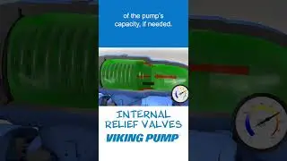
Install the head. Ensure that the relief valve is oriented toward the suction port.
Place a brass or hardwood bar into the port opening to keep the pump from turning. Torque the lock nut to the appropriate torque setting. This setting can be found in the technical service manual.
Bend a tang of the lock washer into a slot of the lock nut. If no tang aligns, continue to tighten the lock nut until one does. Failure to tighten the locknut or engage the lock washer tab could result in early bearing failure and cause damage to the rest of the pump.
You can now set the end clearance. The end clearance setting can be found in the technical service manual. Please refer to our video “Setting End Clearance” for details on this procedure.
Turn the shaft to ensure the pump turns freely.