Finding out a 0.5 Watt Class A audio amplifier, how does that work? Experiment, schem. & explanation
Please read the description first. Much more info is there + an update.
DEFINITE circuit (5 nov. 2024) is here • Class A 150 - 300 mW audio amplifier,...
Because everything is explained in the video and it only shows how to do electronic experiments (in this case….btw) I don’t elaborate more.
Some important things and corrections (! / update 5 nov. 2024):
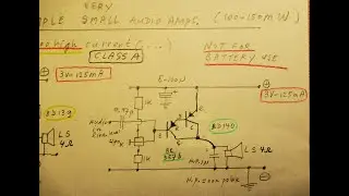
correction: don't bridge the 2 parralleled resistors of 1 K (=500 Ohm) used as emitter resistor with a 47 N capacitor. I found that, without that cap. it works better (forget what I told about that in this video).
possible adaptation: bridge the 220 K resistor of transistor 1 with a capacitor of 47 N when you want more "loudness" and a softer sound. When you use a series resistor in the order of 1K-3K to the input capacitor (base of transistor 1) you even get more "loudness"
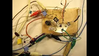
best voltage is 5 Volt. On higher voltages the 2N3055 gets too warm/hot.
connect the emitter of the 2N3055 (on a 5 Volt supply) to ground.
circuit takes 120 mA at 5 Volt.
you can replace the 500 K potmeter with 2 fixed value resistors: one of 220 K from (+) to the base of the BD 140 and one of 330 K from the (-) to that base.
for safety reasons: mount a 500 mA fuse in the supply lead (!)
• The 2N3055 is the best transistor that can/must be used here. Two other good quality NPN end types burnt out for an unknown reason during the development of this circuit.
• Of course you can buy on Ali an amplifier of 0,5 Watt or 1 Watt out for less money, that does the same job, anyway. I don’t think their “loudness properties” can be compared to my analog circuit, because often they are simple Class D amplifiers. No bad words about that, by the way, only that there is (sometimes) HF noise on the audio output or on the voltage supply line. This audio amp. is (only) good as background in a (silent) living room, because of its low audio output (200 mW/300 mW). Though has a nice sound.
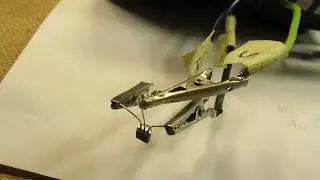
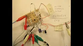
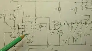
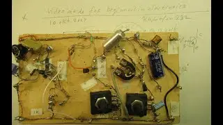
• I always make these sketches first, before drawing a “neat” schematic (when everything is tested and works), to be published on YouTube. This video focuses on that “experimental” stage, thus it gives that first sketch, showing all experimentals. Though, in this case, the sketch will not deviate (much) from the final circuit. Though I have to do some more experiments (see above in this textbox, the update of 5 nov. 2024).
The sound of this 3 transistor Class A audio amp. is "rich" and satisfying on low audio levels with a good quality Loudspeaker box in a living room, say in the 100 MilliWatt to 300 mW range. At least when you bridge that 220 K resistor with a capacitor of 47 N (0,47 uF). Without that capacitor the sound does not have "loudness". You can experiment with the value of that capacitor (higher or lower values).
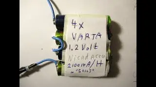
With a series resistor in the order of 1K-3 K connected to the input capacitor (0,22 uF) the sound even gets more "loudness/bass". Of course (always for good class audio amplifiers): a Voltage supply is necessary without any hum or noise. Not-rechargeable batteries are problematic, because of the high constant current. Circuits of hum free mains supplies are on my YouTube channel.
• 0,22 = 0,22 uF and 220 N is also 0,22 uF and 47 N is 0,047 uF and 1 K = 1000 Ohm and 220 K = 220000 Ohm.
The TPA 3116 Chip (Class D) is in this video of 31 October 2024 • TPA3116 Chip tested: 2x50 W audio, US...
The video of 2 (two) too simple Class A audio amps made with 2 Darlingtons (27 October 2024) is here
• Two too simple 150 mW class A audio a...
My You Tube channel trailer is here: • Radiofun232 on YouTube. Updated month...
When you search, search always “NEWEST FIRST” to get the right overview. You can also search via the “looking glass” on my Channel trailer via keywords like ”audio”, “radio”, “amplifier”, “filter”, “Shortwave”, “transistor”, “FET”, “oscillator”, “generator”, “switch”, “schmitt trigger” etc; so the electronic subject you are interested in.
My books about electronics & analog radio technology are available via the website of "LULU”, search for author “Ko Tilman” there.
DIRECT link to my books is here https://www.lulu.com/search?adult_aud...
Search there, and avoid my circuits that are republished, re-arranged, re-edited on other websites, giving not probable re-wiring, etc. Some persons try to find gold via my circuits. I take distance from all these fake claims. I cannot help that these things happen. Upload 4 november 2024.
HUM FREE power supply is here
• How to make a good hum free electroni...
And there are more video's about how to make a simple power supply for high quality audio circuits, also pre-amps, completely free of hum. Search via the "looking glass" on my Channel trailer or contact me via email.
4 nov. 2024, update 5 november 2024.

![[48FPS] [English Subs] Kobayashi san Chi no Maid Dragon S2 Shorts - Episode 05](https://images.videosashka.com/watch/AVO8qna_4HM)