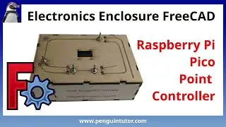
Create laser cut Raspberry Pi Pico case for model railway project - FreeCAD, Inkscape and Lightburn
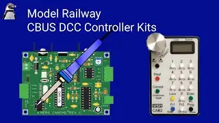
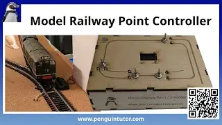
This video shows how I designed a wooden laser cut enclosure for a Raspberry Pi Pico based electronics project. The project is for a points controller for a model railway. It houses two electronics PCBs with the electronics required to control model railway solenoids. It is based around a wood box, which has a sloping top with switches for controlling the points.
The design takes you through the main steps using:
FreeCAD (computer aided design)
Inkscape (vector drawing software)
LightBurn (Laser cutter control software).
Both FreeCAD and Inkscape are free open source software (FOSS), but LightBurn is a commercial paid for application. I'm not aware of a free alternative which works as well as LightBurn, so for now I am using the commercial software for that.
In FreeCAD I used the LC Interlocking (Laser Cutter Interlocking) workbench. However due to the limitations of the plug-in I started the box design in the normal parts workbench before using the LC Interlocking workbench to add the tags.
I then show 3 different techniques for adding holes for the components, and two for how to add writing and etching.
All three tools (FreeCAD, Inkscape and LightBurn) can be used for creating cuts (holes), whereas only Inkscape and LightBurn are used for adding text and drawings which can be etched on the wood.
The video is quite long, but I've split it into a number of chapters for your convenience:
00:00:00 Introduction
00:00:22 Choice of tools – FreeCAD, Inkscape & LightBurn
00:01:22 Box design in FreeCAD LC Interlocking
00:04:18 Box with sloping top – FreeCAD part design
00:19:20 Interlocking tabs with LC Interlocking
00:26:15 Continue in FreeCAD or use Inkscape?
00:27:15 Adding holes in FreeCAD
00:30:35 Flattening the model
00:35:35 Editing using 2D FreeCAD
00:43:30 Exporting from FreeCAD
00:44:05 Using InkScape
00:48:34 Import to LightBurn
00:50:21 Editing in Lightburn
00:55:20 Further editing in InkScape
01:04:56 Loading Inkscape image in LightBurn
01:05:54 Further adjustments in FreeCAD and InkScape