Interpreting Typical Analog Input Control Loop Diagrams
▶ C'mon over to https://realpars.com where you can learn PLC programming faster and easier than you ever thought possible!
=============================
▶ Check out the full blog post over at
https://realpars.com/analog-input
=============================
In this video, we’re going to explain how to read analog input control loop diagrams.
Every industrial control feedback system has 2 loops: an input control loop and an output control loop.
The analog input loop consists of 2 major devices: the transmitter and the controller.
1) The transmitter is the instrument that converts the signal from the sensor to the Process Variable or PV signal which represents the measured variable.
2) The controller is the device that compares the Process Variable or PV and the desired value of the process referred to as the Setpoint.
The analog output loop consists of 2 major devices: the controller and the final actuator.
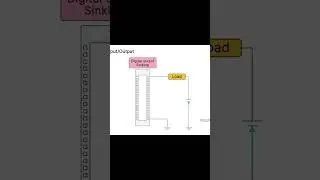
1) When the controller completed the comparison between the Process Variable and the Setpoint, it produces an output signal.
2) The final actuator is the device such as a control valve that exerts a direct influence on the manipulated variable as directed by the signal it receives from the controller.
Alright, now that we’ve discussed the 2 control loops of an industrial feedback control system, let’s look closer at an analog input control loop.
Most analog input control loops are connected in a 2-wire configuration which requires a DC Power Supply.
In some cases, the power supply is external, and in other cases, the power supply is part of the PLC or DCS. The transmitter signal is usually 4 to 20 mA.
Although companies may have different methods of creating Analog I/O Loop drawings, the transmitter, the controller, and the power supply are common to all.
=============================
You might want to review 2 of our other articles:
1) PLC Analog Inputs and Signals (https://realpars.com/plc-analog-inputs/)
2) What are 2-wire and 4-wire Transmitter Output loops? (https://realpars.com/transmitter-wiring/)
=============================
Missed our most recent videos? Watch them here:
https://realpars.com/distributed-io
https://realpars.com/dp-closed-vessel...
https://realpars.com/p-id-symbols/
=============================
To stay up to date with our last videos and more lessons, make sure to subscribe to this YouTube channel:
http://goo.gl/Y6DRiN
=============================
TWEET THIS VIDEO https://ctt.ac/SgOa8
=============================
Follow us on Facebook: / therealpars
Follow us on Twitter: / realpars
Follow us on LinkedIn / realpars
Follow us on Instagram / realparsdotcom
#AnalogIO #RealPars #PLC


![PHARAON–5 минут назад минус [Music Channel]](https://images.videosashka.com/watch/WU1TOKfbQW8)

![[방탄소년단/BTS] 소우주 (Mikrokosmos) 교차편집 (Stage Mix)](https://images.videosashka.com/watch/P1FcNUe7JD4)