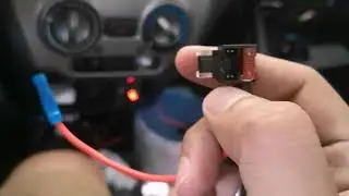
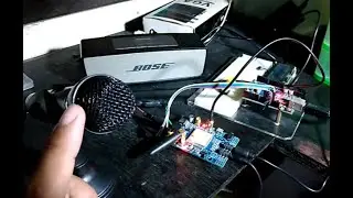
Platinum KS-5 Lunior Lite PCB into a used printing Calculator Keypad
incorporating the Platinum Ks-5 Junior Lite PCB remote into a used printing calculator keypad. Cool isn't it?
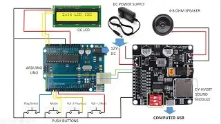
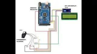
Here is my wiring diagram:
IC PIN# - LABEL
14 and 24 = "1"
14 and 23 = "2"
5 and 20 = "3"
16 and 24 = "4"
16 and 23 = "5"
4 and 20 = "6"
21 and 23 = "7"
2 and 14 = "8"
2 and 15 = "9"
1 and 14 = "0"
2 and 21 = "OK"("PLAY")
20 and 23 = "RESERVE" this is a coin switch
3 and 19 = "STOP"
3 and 18 = "CANCEL"
5 and 15 = "MELODY"
1 and 20 = "BGV" background video
??? = "TEMPO (+)" sorry i can't find this on the pcb
17 and 24 = "TEMPO (-)"
5 and 17 = "KEY b"
6 and 15 = "KEY #"
??? = "POWER" i also cannot find this one :)
4 and 21 = "MUTE"
2 and 16 = "VOL (+)"
3 and 17 = "VOL (-)"
??? = "MIC (+)" also this one
3 and 14 = "MIC (-)"
That's it!. Hope this can help you out on your board if you bought this pcb as well..
Actually there are 64 possible wiring connections to make on the PCB. I found 24 connections that are working. There are also redundant connections like key#, keyb, melody, clear, search, stop, title, 9,3,7,2, and 5.
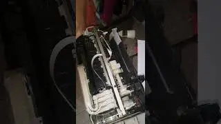
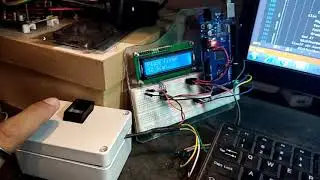
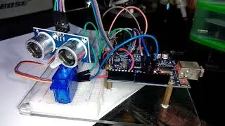
Here's my prototype
• KS-5 Junior Lite DIY Keypad
I bought the pcb circuit from here:
https://s.lazada.com.ph/s.Tmjb
Enjoy!


![[2] Umugani w'Ibimanuka byategetse u Rwanda. Ukuri kurimo ni ukuhe? Ibisobanuro bya F. Rudakemwa](https://images.videosashka.com/watch/H38VPFSRC9g)